Let There Be Shadows (Part II)
March 16, 2007
New York, N.Y.
After I posted my previous feasibility study on doing shadows in WPF 3D, I received helpful emails from Larry O'Brien and WPF 3D Blogger Jordan Parker, both of whom induced me to think of the problem in another way. Thank you!
I am happy to report that this morning I implemented an approach I'm quite happy with.
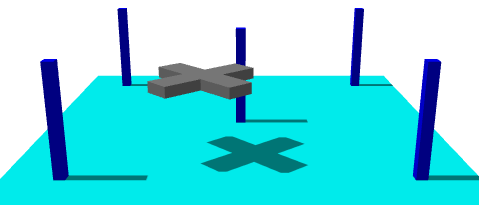
The "chopper" is animated, of course. Besides actually having good performance without jaggies on the shadow, what makes this especially cool is that it happens to be an all-XAML solution:
This comes under the category of "putting the API to work." Basically, the cyan "ground" or "floor" is covered by a second material which is based on a VisualBrush, the visual being basically another Viewport3D that views the figures from the perspective of the DirectionalLight. This brush is the shadows.
This is certainly not a generalized scheme for 3D shadows. First, the scene must be divided into figures that throw shadows and figures that display shadows. The figures that throw shadows here are the five "pillars" (which I originally put in to help me ensure that my math was correct) and the "chopper." These figures do not throw shadows on each other. The figure that displays the shadows (the "ground" in this example) must be flat and rectangular.
It also became evident to me that unless I wanted to get into some math that my poor Friday-morning head wasn't ready for, the direction vector of the light had to be parallel to one side of the "ground." I normally like to use a DirectionalLight vector of (2, -3, -1) but for this file I set it to (2, -3, 0) so it's parallel to the XY plane.
Much of this 3D scene is defined as resources. In particular, all the figures that throw shadows — the five pillars and the chopper — are part of a single Model3DGroup. Because this is a "model" it can be shared among multiple visuals, and indeed it is.
For the moment let me skip the final resource (of type Border named "lightview") and take you through the main Viewport3D. It begins with the definition of the "ground," which is a rectangle on the XZ plane centered at the origin and extending 2 units on the negative and positive X and Z axes. That figure is covered by two DiffuseMaterial brushes, one of which uses a simple Cyan brush, and the other which uses a VisualBrush based on the "lightview" resource. The Model3DGroup containing the pillars and chopper becomes a single line in the Viewport3D. Notice that the lighting is divided equally between AmbientLight and DirectionalLight with the aforementioned Direction vector of (2, -3, 0).
The XAML file concludes with three animations that spin the chopper around the scene. As all of us who have been poisoned inspired by the "everything is animatable" rule know, WPF 3D shadows that can't be animated in real time have to be considered totally worthless.
The shadowing logic is implemented entirely in that tiny "lightview" resource. As you can see, it's basically another Viewport3D based on that same Model3DGroup containing the pillars and the chopper (but not the ground). There are no lights, which means that the figures in this scene will be rendered as black. This Viewport3D is a view of the figures from the perspective of the DirectionalLight. Because DirectionalLight is assumed to come from infinity, this Viewport3D uses OrthographicCamera. (A scene lit by PointLight would use a regular PerspectiveCamera for the shadows.) The LookDirection vector is the same as the Direction vector of the DirectionalLight. The Position property is set so that the center of the camera view is the origin, which is the center of the ground. Because this is an OrthographicCamera pointing to the origin, the coordinates of the Position property can be doubled or tripled with no effect on the scene. The camera just needs to be back far enough so the figures are in front of it.
I defined the TextureCoordinates for the ground so that the upper-left corner of the brush corresponds to the left-rear corner of the ground. The OrthographicCamera of this Viewport3D is positioned at the point (-2, 3, 0) and looking towards the origin. To make the left-rear corner of the ground correspond to the top-left corner of the Viewport3D the camera has to be oriented so that the top of the camera — the UpDirection property — points to the negative Z axis: the vector (0, 0, -1).
The Width property of the OrthographicCamera needs to be set so that the width of the ground (which is 4 units in size) fits precisely within the width of the Viewport3D with the camera oriented at an angle to the ground. This is just a little trig problem, and you'll discover that Width should be set to 3.33. Here's a little diagram of the calculation, a cross-section looking in the -Z direction:
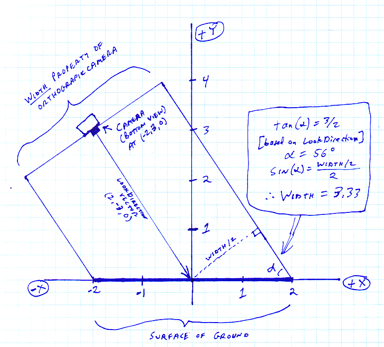
This is a crucial calculation; otherwise the shadows won't line up with the figures,
Regardless, if you just use a Viewport3D as the Visual property of a VisualBrush you'll find that the visual parts of the 3D scene expand to fill the brush. For that reason, I enclosed the Viewport3D inside a Border element, which is given a particular size in device-independent units and a Transparent background. The actual dimensions of this Border are less important than its aspect ratio. I gave it a Height of 400 units corresponding to the 4-unit depth of the ground, and a Width of 333 units corresponding the 3.33 width viewed by the camera. That 333-by-400 element is then stretched to fill the surface of the ground.
Without any lights in the Viewport3D, the figures are normally rendered as black, which would make for black shadows. Ambient light normally causes shadowed areas to be only darker that non-shadowed areas rather than completely devoid of light, so the Viewport3D is given an Opacity of 0.5, corresponding to the 50/50 split between AmbientLight and DirectionalLight in the scene.
Although I'm happy this technique works, I am most distressed about limiting light to directions parallel to the axes, so I hope fixing that problem will be my next enhancement.