The Mathematics of ArcSegment
January 2, 2008
Roscoe, N.Y.
In the Windows Presentation Foundation, the traditional concept of the graphics path is realized by the abstract Geometry class and its derivatives, most prominently PathGeometry.
A PathGeometry is potentially a collection of connected and disconnected straight lines and curves, some of which might define enclosed areas. The easiest way to render a Geometry object (such as PathGeometry) on the screen is to set it to the Data property of a Path element, also specifying the pen characteristics used to stroke the path, and the brush to fill enclosed areas.
From the programmer's perspective a PathGeometry is a collection of PathFigure objects, each of which describes a single series of connected straight lines and curves. The PathFigure class has a StartPoint property and contains a collection of PathSegment objects. PathSegment is an abstract class from which seven other classes derive: LineSegment, PolyLineSegment, BezierSegment, PolyBezierSegment, QuadraticBezierSegment, PolyQuadraticBezierSegment, and ArcSegment. The first segment in the collection maintained by PathFigure begins at the StartPoint property that the figure defines. Each succeeding segment starts at the last point in the preceding segment. The points where one segment ends and the next one begins are always explicitly specified.
There may come a time when you need to generate polyline approximations to the various types of path segments. The Geometry class itself has a method named GetFlattenedPathGeometry and the PathFigure class has a method named GetFlattenedPathFigure that does this for you, but there might be a reason you want to do it yourself. (For example, you might want an approach that doesn't explicitly or implicitly cause routine memory allocations from the managed heap.)
Polyline approximations to the Bezier and quadratic Bezier curves are well know; the derivation of parametric formulas for these two curves is shown in pages 806 through 812 of my book Applications = Code + Markup.
The ArcSegment, however, is particularly tricky. That's what I'll tackle in this blog entry.
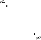
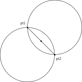
When using ArcSegment, the arc always begins at the end of the preceding segment (or the StartPoint property of PathFigure) and ends at the Point property of ArcSegment. Let's call these two points pt1 and pt2:
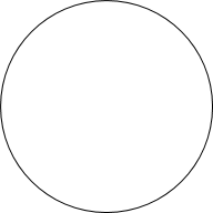
The ArcSegment class also defines a property named Size of type Size. The Width and Height properties of Size specify the horizontal and vertical radii of the ellipse (also known as semimajor and semiminor axes). To keep it simple (initially) let's assume that the two dimensions are equal , resulting in a circle:
Conceptually, the WPF aligns this circle with the two points. In general, there are two ways this can be done:
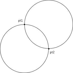
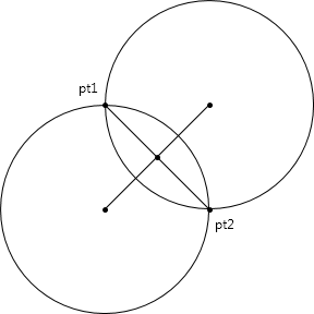
Thus, for a circle of a particular dimension, there are at most four ways to draw an arc from pt1 to pt2. You specify which one you want using the SweepDirection and IsLargeArc properties of ArcSegment. Set the SweepDirection property to one of the two enumeration values SweepDirection.Clockwise or SweepDirection.Counterclockwise. Set IsLargeArc to true if you want the arc that's greater than 180° and false otherwise. Keep in mind that the arc is always drawn from pt1 to pt2, so there's no ambiguity.
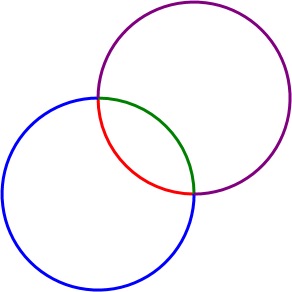
Here are the four possibilities shown in color:
That's from a program in Chapter 28 of Applications = Code + Markup:
I'm sure that a similar program is in every WPF programming book.
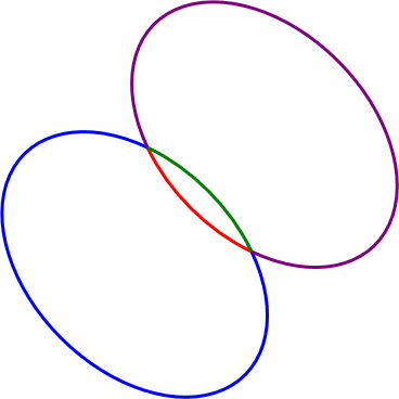
If you need to reproduce the ArcSegment with a polyline approximation, you must determine the center of one of the two circles. The two points are connected by a chord:
Get some information about that chord, including the vector from pt1 to pt2:
-
Point midPoint = new Point((pt1.X + pt2.X) / 2, (pt1.Y + pt2.Y) / 2);
Vector vect = pt2 – pt1;
double halfChord = vect.Length / 2;
Rotate the vector 90°. Which way you rotate it depends on the settings of IsLargeArc and SweepDirection. If the Boolean value of IsLargeArc equals (SweepDirection == SweepDirection.Counterclockwise), rotate it 90° clockwise:
-
vectRotated = new Vector(–vect.Y, vect.X);
Otherwise, rotate it 90° clockwise:
-
vectRotated = new Vector(vect.Y, –vect.X);
And normalize it:
-
vectRotated.Normalize();
That is now a unit vector perpendicular to the chord and pointing to the center of the appropriate circle. Now calculate the distance from the midpoint of that chord to the center of the circle using the Pythagorean theorem. The other two sides are half the length of the chord, and the radius of the circle:
-
double centerDistance = Math.Sqrt(radius * radius – halfChord * halfChord);
You can then find the center point of the circle by multiplying that distance by the rotated vector and adding it to the midpoint of the chord:
-
Point center = midPoint + centerDistance * vectRotated;
Once you have the center point, determine the angles from the center to pt1 and pt2 using Math.Atan2:
-
double angle1 = Math.Atan2(pt1.Y – center.Y, pt1.X – center.X);
double angle2 = Math.Atan2(pt2.Y – center.Y, pt2.X – center.X);
Because Math.Atan2 returns angles in the range of 0 to 2π, you will have to adjust them if IsLargeArc is true, and the absolute value of the difference between the angles is less than π. You'll want to increase the lesser of the two angles by 2π. You're now in a good position to calculate the points of the arc using the common parametric equations for the ellipse.
Here's a FlattenArc method appropriate for a circle. The arguments to the method correspond (roughly) to the properties of ArcSegment but with only one radius.
void FlattenArc(IList<Point> points, Point pt1, Point pt2,
double radiusY,
bool isLargeArc, bool isCounterclockwise,
double tolerance)
{
// Get info about chord that connects both points
Point midPoint = new Point((pt1.X + pt2.X) / 2, (pt1.Y + pt2.Y) / 2);
Vector vect = pt2 - pt1;
double halfChord = vect.Length / 2;
// Get vector from chord to center
Vector vectRotated;
// (comparing two Booleans here!)
if (isLargeArc == isCounterclockwise)
vectRotated = new Vector(-vect.Y, vect.X);
else
vectRotated = new Vector(vect.Y, -vect.X);
vectRotated.Normalize();
// Distance from chord to center
double centerDistance = Math.Sqrt(radiusY * radiusY - halfChord * halfChord);
// Calculate center point
Point center = midPoint + centerDistance * vectRotated;
// Get angles from center to the two points
double angle1 = Math.Atan2(pt1.Y - center.Y, pt1.X - center.X);
double angle2 = Math.Atan2(pt2.Y - center.Y, pt2.X - center.X);
// (another comparison of two Booleans!)
if (isLargeArc == (Math.Abs(angle2 - angle1) < Math.PI))
{
if (angle1 < angle2)
angle1 += 2 * Math.PI;
else
angle2 += 2 * Math.PI;
}
// Calculate number of points for polyline approximation
int max = (int)((4 * (radiusX + radiusY) * Math.Abs(angle2 - angle1) / (2 * Math.PI)) / tolerance);
// Loop through the points
for (int i = 0; i <= max; i++)
{
double angle = ((max - i) * angle1 + i * angle2) / max;
double x = center.X + radiusY * Math.Cos(angle);
double y = center.Y + radiusY * Math.Sin(angle);
Point pt = new Point(x, y);
points.Add(pt);
}
}
Set the tolerance argument to approximately the length of each segment in the polyline approximation. The value of 1 is fine if you're not applying transforms to make the figure much larger.
Obviously I simplified this job a lot by assuming a circle rather than an ellipse. However, an ellipse is really just a circle that's been uniformly stretched in one direction. Given a radiusX and radiusY for the ellipse, it's possible to derive a scaling factor that you can apply to pt1 and pt2 at the beginning of the calculation. At the end of the calculation, you scale the resultant points of the polyline approximation oppositely. Here's an enhanced version of the method (additions in red) that is appropriate for an ellipse:
void FlattenArc(IList<Point> points, Point pt1, Point pt2,
double radiusX, double radiusY,
bool isLargeArc, bool isCounterclockwise,
double tolerance)
{
// Adjust for different radii
Matrix matx = new Matrix();
matx.Scale(radiusY / radiusX, 1);
pt1 = matx.Transform(pt1);
pt2 = matx.Transform(pt2);
// Get info about chord that connects both points
Point midPoint = new Point((pt1.X + pt2.X) / 2, (pt1.Y + pt2.Y) / 2);
Vector vect = pt2 - pt1;
double halfChord = vect.Length / 2;
// Get vector from chord to center
Vector vectRotated;
// (comparing two Booleans here!)
if (isLargeArc == isCounterclockwise)
vectRotated = new Vector(-vect.Y, vect.X);
else
vectRotated = new Vector(vect.Y, -vect.X);
vectRotated.Normalize();
// Distance from chord to center
double centerDistance = Math.Sqrt(radiusY * radiusY - halfChord * halfChord);
// Calculate center point
Point center = midPoint + centerDistance * vectRotated;
// Get angles from center to the two points
double angle1 = Math.Atan2(pt1.Y - center.Y, pt1.X - center.X);
double angle2 = Math.Atan2(pt2.Y - center.Y, pt2.X - center.X);
// (another comparison of two Booleans!)
if (isLargeArc == (Math.Abs(angle2 - angle1) < Math.PI))
{
if (angle1 < angle2)
angle1 += 2 * Math.PI;
else
angle2 += 2 * Math.PI;
}
// Invert matrix for final point calculation
matx.Invert();
// Calculate number of points for polyline approximation
int max = (int)((4 * (radiusX + radiusY) * Math.Abs(angle2 - angle1) / (2 * Math.PI)) / tolerance);
// Loop through the points
for (int i = 0; i <= max; i++)
{
double angle = ((max - i) * angle1 + i * angle2) / max;
double x = center.X + radiusY * Math.Cos(angle);
double y = center.Y + radiusY * Math.Sin(angle);
// Transform the point back
Point pt = matx.Transform(new Point(x, y));
points.Add(pt);
}
}
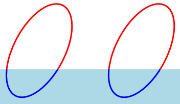
Why use a Matrix object? Couldn't I just have calculated a scaling factor and performed the scaling explicitly? Certainly, but there's still more work ahead: The ArcSegment class includes a RotationAngle property that indicates the rotation of the ellipse before it is fit to the lines. Here's an example of four possibilities of ArcSegment with a non-zero RotationAngle:
The two axes of the ellipse are no longer parallel to the horizontal and vertical. This seems like an enormously complex monkey wrench to throw into the calculation, but everything has been prepped for the amazing feat of taking account of this rotation angle with the addition of just a single statement:
void FlattenArc(IList<Point> points, Point pt1, Point pt2,
double radiusX, double radiusY, double angleRotation,
bool isLargeArc, bool isCounterclockwise,
double tolerance)
{
// Adjust for different radii and rotation angle
Matrix matx = new Matrix();
matx.Rotate(-angleRotation);
matx.Scale(radiusY / radiusX, 1);
pt1 = matx.Transform(pt1);
pt2 = matx.Transform(pt2);
// Get info about chord that connects both points
Point midPoint = new Point((pt1.X + pt2.X) / 2, (pt1.Y + pt2.Y) / 2);
Vector vect = pt2 - pt1;
double halfChord = vect.Length / 2;
// Get vector from chord to center
Vector vectRotated;
// (comparing two Booleans here!)
if (isLargeArc == isCounterclockwise)
vectRotated = new Vector(-vect.Y, vect.X);
else
vectRotated = new Vector(vect.Y, -vect.X);
vectRotated.Normalize();
// Distance from chord to center
double centerDistance = Math.Sqrt(radiusY * radiusY - halfChord * halfChord);
// Calculate center point
Point center = midPoint + centerDistance * vectRotated;
// Get angles from center to the two points
double angle1 = Math.Atan2(pt1.Y - center.Y, pt1.X - center.X);
double angle2 = Math.Atan2(pt2.Y - center.Y, pt2.X - center.X);
// (another comparison of two Booleans!)
if (isLargeArc == (Math.Abs(angle2 - angle1) < Math.PI))
{
if (angle1 < angle2)
angle1 += 2 * Math.PI;
else
angle2 += 2 * Math.PI;
}
// Invert matrix for final point calculation
matx.Invert();
// Calculate number of points for polyline approximation
int max = (int)((4 * (radiusX + radiusY) * Math.Abs(angle2 - angle1) / (2 * Math.PI)) / tolerance);
// Loop through the points
for (int i = 0; i <= max; i++)
{
double angle = ((max - i) * angle1 + i * angle2) / max;
double x = center.X + radiusY * Math.Cos(angle);
double y = center.Y + radiusY * Math.Sin(angle);
// Transform the point back
Point pt = matx.Transform(new Point(x, y));
points.Add(pt);
}
}
The ArcSegmentMathDemo project tests it out. This project contains a class named PolylineArc that derives from Shape. It defines five properties (most of them duplicated from ArcSegment) and just draws an arc. The easiest way to write such as class is to return a PathGeometry containing a PathFigure containing an ArcSegment from the required DefiningGeometry override. Instead, PolylineArc returns a PathGeometry containing a PathFigure containing a PolyLineSegment with points calculated from FlattenArc. A XAML file contains two instances of Path with normal arc geometries and two parallel instances of PolylineArc. The RotationAngle is animated so the figures seem to bob in the water in harmonious synchronization:
The downloadable project creates an EXE but here's an XBAP if you just want to run it: