Graphical Paths with Gradient Colors
February 5, 2009
New York, N.Y.
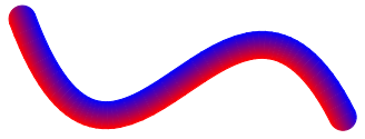
In WPF, you can draw a graphical path (in this case, a Bézier spline) with a thick width (24 units here) and the Stroke property set to a LinearGradientBrush:

It almost looks as if the gradient goes from one end of the Bézier spline to the other, but that's only because the spline is roughly oriented with the LinearGradientBrush. The paradigm used in WPF is that the brush encompasses the entire area occupied by the graphical object, which then works like a stencil to let the color come through:

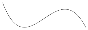
If the Bézier spline were altered somewhat, the sense that the gradient goes from one end to the other would be revealed as an illusion:

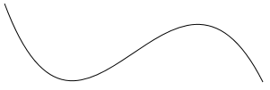
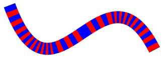
You might prefer that you have the option to draw graphical paths with a gradient brush that truly runs from one end of the figure to the other:

regardless how the Bézier spline is oriented:

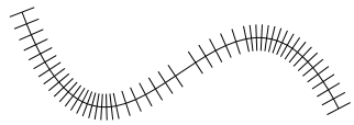
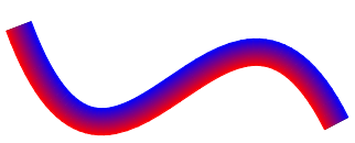
You might instead prefer applying a gradient that is perpendicular to the path rather than parallel with it:
Those last three screen shots display a GradientPath class I wrote. You can play around with this class in a Xaml Browser Application (XBAP) here:
The sample app creates a PathGeometry consisting of a straight line, a Bézier spline, and another straight line. You can change all of the points defining the path by dragging the gray dots, and yes, you can deform the figure to a point where the drawing logic breaks down. But if you keep the figure fairly continuous without sharp bends, it pretty much works.
You can download the GradientPathDemo source code. The GradientPath class derives from FrameworkElement and defines eight properties:
-
Data of type Geometry has the same role as in the Path class.
-
GradientStops of type GradientStopCollection is a collection of GradientStop objects, just as in LinearGradientBrush and RadialGradientBrush.
-
ColorInterpolationMode of type ColorInterpolationMode works the same as in LinearGradientBrush and RadialGradientBrush
-
GradientMode of type GradientMode, an enumeration with two members, Parallel and Perpendicular as shown in the examples above.
-
StrokeThickness of type double determines the width of the line.
-
StrokeStartLineCap and StrokeEndLineCap of type PenLineCap determine the appearance of the ends of the line.
-
Tolerance of type double governs the precision that the path is approximated by a polyline.
Most of the action in GradientPath occurs in the OnRender override. When this method is called, the Data property of the class is set to a Geometry, which might look like this:
The OnRender method begins by converting that Geometry to a flattened PathGeometry by calling the GetFlattenedPathGeometry method:
A flattened PathGeometry approximates a Geometry with polylines. It might contain multiple PathFigure objects, but each PathFigure contains only a single PolyLineSegment in its Segments collection.
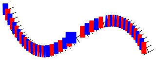
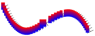
At each point in the polyline approximation a perpendicular is determined. This perpendicular is StrokeThickness units in length, and is actually the average of the perpendiculars of the little line segments on each side of the point:
Each pair of adjacent perpendiculars defines a tetragon (alternately color blue and red here for illustrative purposes):
Each of those tetragons must be colored with a gradient brush. (For the remainder of this description I'll use the Perpendicular mode which happens to be algorithmically simpler.) I tried a couple different approaches here, but the best one involved first rotating the tetragon so that the original line segment through its center is horizontal:
This rotated tetragon gets a LinearGradientBrush that goes from top to bottom:
And the resultant object is rotated back into place:
Coloring the little tetragons for the Parallel mode was a little more complicated because each of the little figures must contain only a portion of the total gradient. I did this by creating a new GradientStops collection and modifying each Offset based on the ratio of the length of the polyline segment to the total length of the figure.
The line caps had to be handled separately, and here again, the Perpendicular mode was much easier. For the Parallel mode I didn't try to gradate the caps at all, but instead determined an appropriate color based on Offset values of 0 (for the StrokeStartLineCap) and 1 (for the StrokeEndLineCap). There is no guarantee that the GradientStops collection will actually contain GradientStop objects with those precise Offset values, so I had to perform the interpolation myself.
I regret to say that GradientPath has a problem if one of the gradient colors is transparent or partially transparent. In WPF, if two filled polygons share an edge (and this edge is not horizontal or vertical), there will often be a slight visual gap between the two figures. To avoid this gap between the tetragons, I not only filled the path, but stroked it with a pen that is outlinePenWidth units wide (defined as a constant 1 in the GradientPath class) and the same brush as the fill. However, this causes the tetragons to overlap slightly, and when there is partial transparency, the overlap shows up as a darker line.
I tried fiddling with different values of outlinePenWidth, but nothing seemed to work well for both non-transparent and transparent colors.