Bézier Circles and Bézier Ellipses
December 6, 2012
New York, N.Y.
About 11 years ago, while writing my first book about Windows Forms programming, I became interested in the technique of rendering circular arcs using Bézier curves, and I read a couple articles on the subject from one of the many periodicals available at the New York Public Library:
-
Tor Dokken, et al, "Good Approximation of Circles by Curvature-Continuous Bézier curves," Computer Aided Geometric Design 7 (1990), 33-41.
-
Michael Goldapp, "Approximation of Circular Arcs by Cubic Polynomials," Computer Aided Geometric Design 8 (1991), 227-238.
As you know, a cubic Bézier curve in two dimensions is described by four points. The curve passes through the two endpoints p0 and p3, while p1 and p2 are control points that seem to pull the curve in their directions. When using a Bézier curve to draw a circular arc, p0 and p3 are points on the circle, and the two control points lie outside the circle. Here are those four points defining the arc of a pie slice that is 1/8th of a circle:
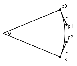
The lines from p0 to p1 and from p3 to p2 are tangent to the circle, and hence at right angles to lines from the center of the circle to the endpoints. This means that a vector describing the direction of these lines from the endpoints to the control points is easily calculable by rotating the vectors from the circle's center to the endpoints by 90 degrees. (A 90 degree rotation of a normalized vector is pretty easy because you merely swap the X and Y coordinates of the vector and make one of them negative.) The hard part is the length of those lines from p0 to p1 and from p3 to p2, which I've labeled with the letter L.
The first article cited above indicates that a fairly good approximation results from:
L = 4 * tan(α / 4) / 3
times the radius of the circle, where the angle α is in degrees. For the above diagram, α is 45 degrees, so L is 0.265, and you can see that the length of these lines is approximately 1/4 of the radius.
The calculations of the two control points becomes exceptionally easy when the angle is 90 degrees, and the two endpoints are at the top and sides of the circle:
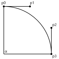
The Y coordinates of p0 and p1 are now the same, as are the X coordinates of p2 and p3, and L is about 0.55. If the radius is 100, then the control points are 55 units from the endpoints, which is fairly easy to remember. Only four Bézier curves are required to define a whole circle.
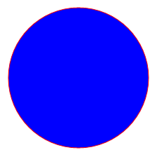
How well does this approximation work? Let's try a little XAML. This is for Windows 8 but it can be adapted to any XAML-based framework. Two 100-pixel radius circles are drawn, one by a Path and an EllipseGeometry filled with blue, the second by a Path, PathFigure and four BezierSegment objects stroked with red. In both cases the center of the circle is (0, 0) which is centered in the window using a technique I like involving centering a collapsed Canvas:
<Page x:Class="BezierCircle.MainPage"
xmlns="http://schemas.microsoft.com/winfx/2006/xaml/presentation"
xmlns:x="http://schemas.microsoft.com/winfx/2006/xaml">
<Grid Background="White">
<Canvas HorizontalAlignment="Center"
VerticalAlignment="Center">
<Path Fill="Blue">
<Path.Data>
<EllipseGeometry Center="0 0"
RadiusX="100"
RadiusY="100" />
</Path.Data>
</Path>
<Path Stroke="Red">
<Path.Data>
<PathGeometry>
<PathFigure StartPoint="0 -100"
IsClosed="True"
IsFilled="False">
<BezierSegment Point1="55 -100"
Point2="100 -55"
Point3="100 0" />
<BezierSegment Point1="100 55"
Point2="55 100"
Point3="0 100" />
<BezierSegment Point1="-55 100"
Point2="-100 55"
Point3="-100 0" />
<BezierSegment Point1="-100 -55 "
Point2="-55 -100"
Point3="0 -100" />
</PathFigure>
</PathGeometry>
</Path.Data>
</Path>
</Canvas>
</Grid>
</Page>
Of course I could have used a single PolyBezierSegment for the circle's outline, but it's probably more helpful to see the actual coordinates for each segment of the total curve.
If the Bézier approximation is "good enough," the red circle should outline the blue interior without any white background peaking through on the inside, or any blue visible outside the red circumference. That appears to be the case:
Recently I received an email from a reader of Programming Windows 6th edition about applying this technique to ellipses. It's always helpful to remember that an ellipse is a circle that's been stretched in one direction, and possibly rotated (if the axes aren't parallel to the coordinate system). Regardless how a circle has been constructed, you can turn it into an ellipse by applying a ScaleTransform. Or, if you're using an EllipseGeometry, by setting different values of the RadiusX and RadiusY properties. Or, if you're defining a circle from Bézier curves, by uniformly scaling the X or Y coordinates of the points defining the curves.
The following XAML file is very similar to the first one except that RadiusX is set to 300 and all the X coordinates of the points contributing to the Bézier curve have been increased by a factor of 3:
<Page x:Class="BezierEllipse.MainPage"
xmlns="http://schemas.microsoft.com/winfx/2006/xaml/presentation"
xmlns:x="http://schemas.microsoft.com/winfx/2006/xaml">
<Grid Background="White">
<Canvas HorizontalAlignment="Center"
VerticalAlignment="Center">
<Path Fill="Blue">
<Path.Data>
<EllipseGeometry Center="0 0"
RadiusX="300"
RadiusY="100" />
</Path.Data>
</Path>
<Path Stroke="Red">
<Path.Data>
<PathGeometry>
<PathFigure StartPoint="0 -100"
IsClosed="True"
IsFilled="False">
<BezierSegment Point1="165 -100"
Point2="300 -55"
Point3="300 0" />
<BezierSegment Point1="300 55"
Point2="165 100"
Point3="0 100" />
<BezierSegment Point1="-165 100"
Point2="-300 55"
Point3="-300 0" />
<BezierSegment Point1="-300 -55 "
Point2="-165 -100"
Point3="0 -100" />
</PathFigure>
</PathGeometry>
</Path.Data>
</Path>
</Canvas>
</Grid>
</Page>
And here's the result:
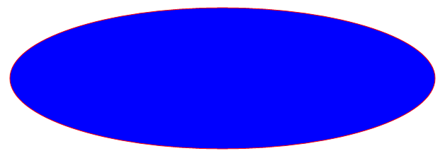
Again, the approximation if visually fine.
|
Programming Windows, 6th Edition
For one price, get the Release Preview ebook |